Amazing, isn’t it! That tiny microcontroller is actually able to talk to the computer! And to communicate, there’s a protocol – meaning a specific way to talk. For this data communication, we’ll use serial communication. To learn more about serial communication, you can read: How Microcontrollers Communicate Data…, and for the project, we’re using ATMEGA16 (8MHz), a MAX232 IC, a DB9 Female connector, and some random accessories.
MAX232:
To communicate with the computer, the microcontroller uses serial communication. However, serial communication can’t work over long distances. At that point, it piggybacks on another protocol called RS232, which can travel quite far. And the computer simply cannot receive serial communication without the RS232 protocol. So, to connect the two protocols, you need to convert once in between. MAX232 comes into play as the mediator, constantly converting data from one protocol to the other. The whole process looks like this,


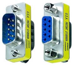
For serial communication, a connector called DB9 is used to connect the computer’s parts with the microcontroller’s components. Here’s how it looks:

There are two variations: male and female. The picture above, along with the pin diagram, should make it clear.
Project Overview:
Our task is to send a few commands from the computer. For example,
| Command | Function |
| ON | The LED will light up |
| OFF | The LED will turn off |
| GET | The current status of the LED will be reported to the computer. ON: LED is ON OFF: LED is OFF |
Electronics:
In the first part of this project, we’ll show how to use serial communication with a microcontroller. Pins 14 and 15 on the ATMEGA16 are the receiver and transmitter pins for serial communication, respectively. These pins are responsible for receiving or sending serial data. As mentioned earlier, the computer won’t understand this raw serial data. It needs to be converted to the RS232 protocol. So, pins 14 and 15 are connected to pins 12 and 11 on the MAX232, which handle the serial data for the MAX232. Then, pins 14 and 13 on the MAX232 are the RS232 data lines, carrying the data just converted from serial. These data lines go to the computer through a DB9 female connector. Here’s the basic connection diagram for the MAX232:

Here’s the connection for the entire circuit (there’s also an LED included):

There are two more things to mention. In the above diagram, there are two components called Terminal 1 and Terminal 2, which are just for debugging or testing purposes. For example, if you type ON and hit Enter in Terminal 1, the D1 LED lights up; if you type OFF, it turns off. You can imagine Terminal 1 as the computer. Terminal 2, on the other hand, displays what data is coming into the microcontroller from Terminal 1. To run the simulation in Proteus, you need to enter the commands in Terminal 1 as listed in the table above. Similarly, if you type GET and press Enter, the current LED status (ON or OFF) will be displayed in the terminal. To learn more about the Proteus software, you can read: Fun Circuit Building Software: Proteus.
Programming:
The code uses the serial communication library of MikroC. Let’s take a look at the code:
[code]
void main() {
      char buffer[10];
      char i;

      DDB0_bit = 1;
      PORTB0_bit = 0;

      UART1_Init(9600);
      Delay_ms(100);

      while (1) {
            if (UART1_Data_Ready()) {
               UART1_Read_Text(buffer, "r", 8);

               for (i=0; i                   buffer[i] = tolower(buffer[i]);
               }

               if (!strcmp(buffer, "on")) {
                  PORTB0_bit = 1;
               } else if (!strcmp(buffer, "off")) {
                  PORTB0_bit = 0;
               } else if (!strcmp(buffer, "get")) {
                 if (PORTB0_bit) {
                    UART1_Write_Text("ONrn");
                 } else {
                    UART1_Write_Text("OFFrn");
                 }
               }
            }
      }
}
[/code]
Explanation:
The microcontroller checks whether any serial data has been received. If so, it follows the command as per the table above. If needed, it also transmits the LED’s status.
The next part will include connecting to the computer and sending commands from the computer.
File:
Courtesy: Jontropati.com


ধন্যবাদ
Protious install korar por kisu error dekhasse… maybe ami thik vabe patch korte pari nai.
Onek onek thanks ai post tar jonno. 🙂
Rashed@ Clipping Path India.
ভাই একটু সাহায্য করবেন? আমি পলিটেকনিক এ electronics এ চান্স পেয়েছি. কিন্তুু অনেকেই বলে এ খানে পরে কোন ফাইদা নাই.চাকরি হায় না বল্লেই চলে. আর হলেও নাকি বেতন ভালোনা. এখন কি কারব বুঝতে পারিনা. একটু সত পরামর্শ দিন pls. ([email protected]) এ দয়াকরে জানান.
ভাই আপনার থেকে একটু সত পরামর্শ নিতে চাই ছোট ভাই হিসেবে. দয়া করে দিবেন. কারণ এটার উপর আমার ভবিষ্যৎ জীবন নির্ভর করবে. আমি পলিটেকনিক এ ইলেক্ট্রনিক্স এ চান্স পেয়েছি. এখন অনেকেই বলে পলিটেকনিক এ পড়লে নাকি জীবন বাত হইয়া জায় এবং এই সাব্জেক্ট এর উপর বেশি চাকরি নাই.আর থাকলেও নাকি বেতন ভালো না. তাই এখন কি করব বুঝতে পারতাছিনা. তাই একটা ভালো পরামর্শ দিন. pls pls pls pls :- e-mail :[email protected]
অনেক তথ্যবহুল লেখা লিখেছেন। কিন্তু প্রোটিয়াস সফটওয়্যার একটি পেইড সফটওয়্যার। এটা ইনস্টল করা সাধারন মানুষের পক্ষে একটু কষ্টকর। এই বিষয় নিয়ে আশা করছি পরবর্তি কোন লেখাতে মাথায় রাখতে অনুরোধ করা হচ্ছে। অনেক সুন্দর হয়েছে লেখাটি ভাই। ইলেক্ট্রনিক্স বিভাগের ছাত্র-ছাত্রীদের ক্ষেত্রে খুবই মূল্যবান একটি পোস্ট।
এভাবেই লিখে জান। শুভকামনা রইলো।
maybe ami thik vabe patch korte pari nai.
Onek onek thanks ai post tar jonno. @ http://pcjobs24.com/